Installation Guidelines & FAQ + Terms of Sale
We hope you find these instructions useful and helpful. we also have a quick link to our companies agreed terms of sale. If you need further explanation on installation please email us sales@octopustvenclosures.com.au or call 0488 009 001
Click Here - Agreed Terms of Sale
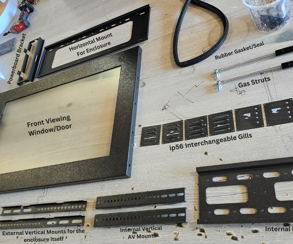
Below is a list of the main parts which make up the Octopus TV Enclosures.
1. Front Viewing Window/Door
2. Powerboard bracket
3. Horizontal Mount for Enclosure
4. Rubber Gasket, Seal
5. Gas Struts x 2
6. IP56 Interchangeable Gills
7. External Vertical Mounts for the enclosure itself
8. Internal Vertical AV mounts
9. Internal Enclosure Bracket
NOTE: Cable Entry
NOTE: Direct Sunlight Applications
NOTE: Enclosure Limitations
NOTE: Enclosure ID Chart
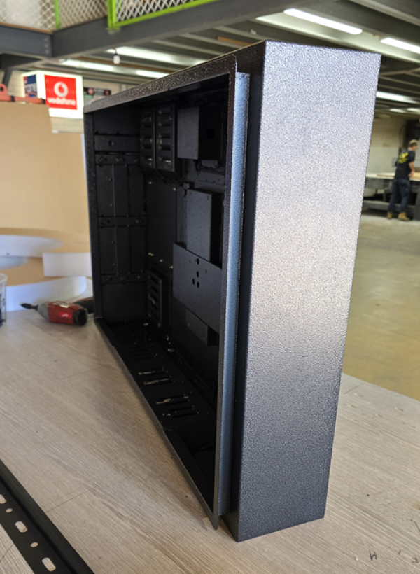
Other parts not shown include main enclosure rear side housing, thermostat PCB control board, general wiring, power supply, fans, powerboard, rubber drainage plug holes, key locks and top brackets.
ALL Enclosures are supplied KEYED ALIKE
Indoor | Outdoor TV Enclosures
GUIDE 1: Installing the Enclosure
We recommend prior to lifting and installing the entire enclosure in one piece, rather from experience that you remove the front viewing window/door first. This is done by disconnecting the gas struts x 2 and taking off the top hinges (using a screw driver) open/close the enclosure door. This makes lifting very lightweight and provides an easier installation. The image on the right highlights the front door being removed, thus leaving you with the main enclosure chassis to install.
Remove enclosure from the packaging, use packaging to place enclosure face up.
Unlock enclosure
Disconnect gas struts x 2
Unscrew top hinges from the enclosure front door
Remove the front door and place it somewhere safe
Now you can take the rear chassis and mount it to the wall
After you make all connections like power/data/coax, you can plug everything into the enclosure powerboard, look at spacing according to steps in this guide (Guide 4. Spacing) and when happy with it all the front door is the last item you should put back as it was in the box when you first opened it.
Lock the enclosure and power on.
PROCEED TO THE NEXT INSTRUCTIONS BELOW TO MOUNT THE HORIZONTAL BAR ONTO THE WALL
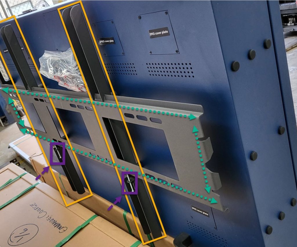
The vertical mounts shown on the right hand side highlighted in “orange” have been preinstalled. They are already attached to the enclosure and ready.
The horizontal bar shown on the right highlighted in “green” is the bracket you need to attach to the wall. Wall can be timber stud, steel stud, brick or concrete. Use appropriate mechanical fixtures where possible – some have been supplied not all.
Once you have levelled and mounted the “green” horizontal bar you can then lift and hook the enclosure onto the horizontal bar
To LOCK the enclosure from being removed use a long Philips head screw driver to tighten the area highlighted in “purple” in the illustration.
GUIDE 2. Installing the Drainage Plugs & Holes
CAUTION: PLEASE TAKE NOTE
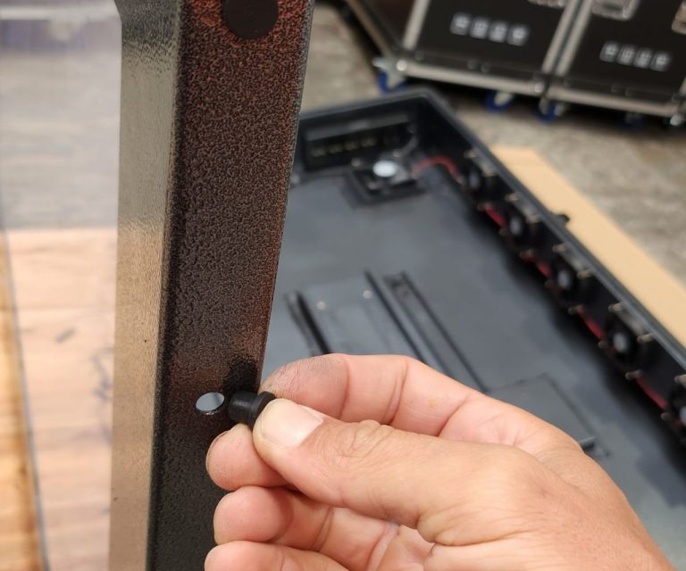
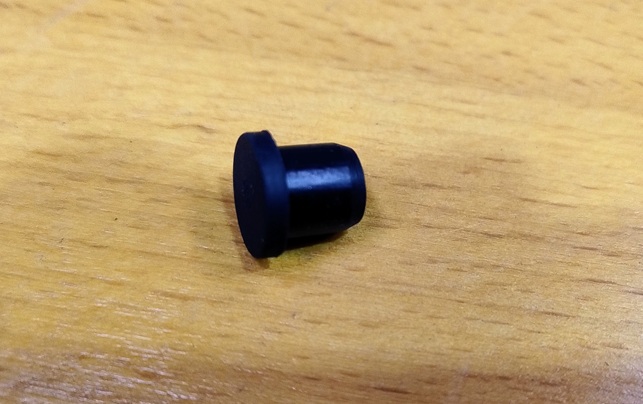
End of year 2022 models all have drainage plugs pre-drilled for you. If they are NOT in use make sure you use rubber plugs in the spare parts package to plug up the holes.
Portrait Mode – Use rubber plugs in spare parts package to plug up all holes on the right side of enclosure. Leave the bottom holes open
Landscape Mode – Use rubber plugs in spare parts package to plug up all holes on the left side of the enclosure. Leave the bottom holes open.
- Please refer to image on the right on how to plug up holes
- Rubber plugs are in the plastic spare parts package
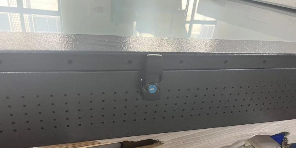
If you are installing the TV enclosure in direct sunlight and it has no shroud, awning or cover we recommend the following. Because most enclosures are black they will attract a lot of heat, especially in summer and it will also be exposed to ‘acts of god’ such as heavy rain fall for long periods of time.
For those reasons we are advising you to ensure that there are some draining holes added to the south side of the enclosure just in case some water may enter – the illustration on the right shows an example of how we do that. It is a safety precaution only. We cannot warrant against ‘acts of god’ or extreme weather conditions. In direct sunlight we recommend you purchase an enclosure in white or light grey and have some cover to assist with performance and longevity of the enclosure.
GUIDE 3. How to adjust fans on/off, temperature setting?
Note: Applicable to 2020 Hybrid Model portrait & landscape TV enclosures
- Adjust control fans by the following:
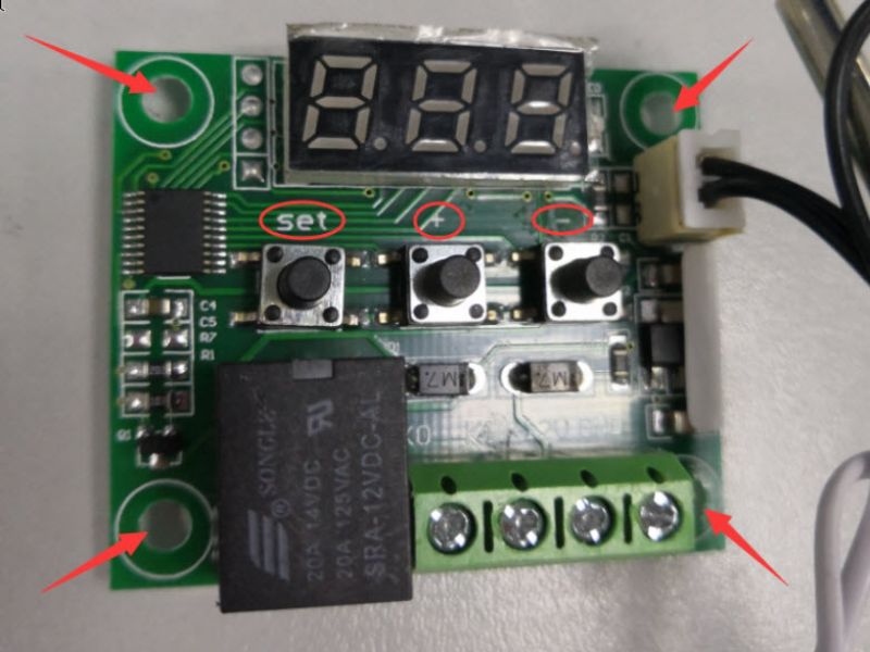
First you must find the thermostat controller (located to the left inside the enclosure) and remove it from it being mounted on the side. - Leave it connected to power etc. Turn ON the enclosure.
- Find the “set” button and press it, the LED light will be flashing, then you can increase/decrease the temperature by “+” or “-“
- Once you select the temp lets say 10 degrees then hit set to apply the new temp setting.
GUIDE 4. Spacing your TV forward or back inside the enclosure - Depending on your TV's depth
VERY IMPORTANT
“To improve the performance and viewing of the TV you should try to mount the TV as close to the front viewing glass as possible – leave at
least a 1cm gap between front of TV and front of the enclosure glass for air flow”.
When the enclosure is closed and locked, if the TV is sitting far away OR far back from the front viewing glass this reduces the
performance of the image/video, thus increasing glare and distorts visual display of the TV inside.
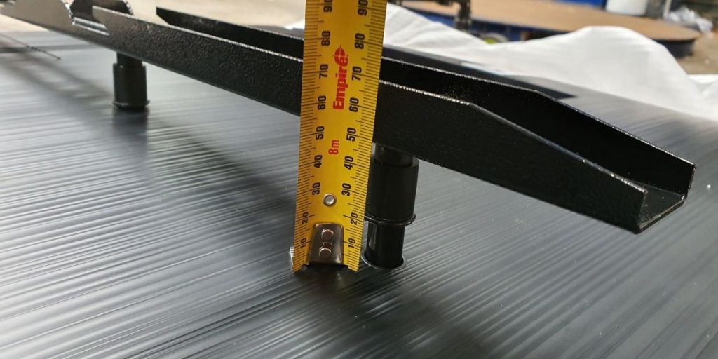
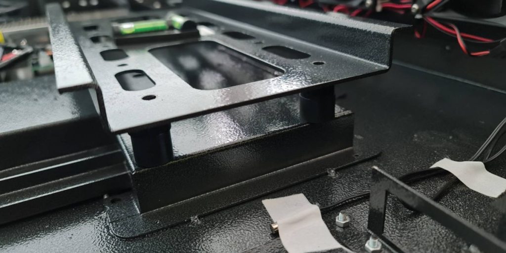
All televisions have different total depths. New tv’s are thinner, but old tv’s are thicker. We do not know which TV you are supplying inside the enclosure. In the example to the right we are showing you a 55” Samsung model that is 60mm in total depth.
Therefore, in order to get the best possible performance from the TV we are using we are going to use plastic spacers and/washers (or similar) to push the TV forward. The illustrations below show how you can do this.
NOTE: Longer bolts may need to be purchased. In the example below we used M8 x 100mm and M8 x 75mm
GUIDE 5. Hybrid 2in1 Model (Landscape Mode Vs Portrait Mode)
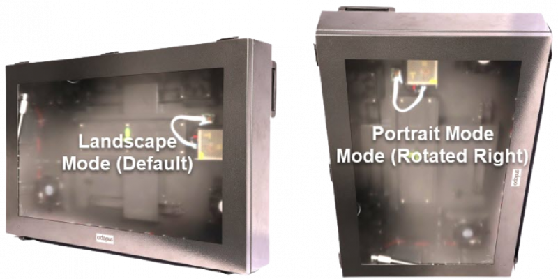
All enclosures are shipped by default in landscape mode
Landscape Mode
Logo aligned bottom middle centre
Rear side carry handles top right and top left
Power supply and power board right side mounted
Locks positioned southside underside of enclosure
IR is bottom left side for convenience
TV is installed left to right
Landscape mode is the traditional way of TV alignment
Portrait Mode
Enclosure needs to be rotated to the right side
Logo is now on the right side
IR is now located on the bottom right side
Power supply and power board is located at the top of the enclosure
Power supply and power board are to be OFF the bottom floor of the enclosure at all times – that means either east or north direction.
Portrait mode typically used for advertising
GUIDE 6. Setup & Position the IR
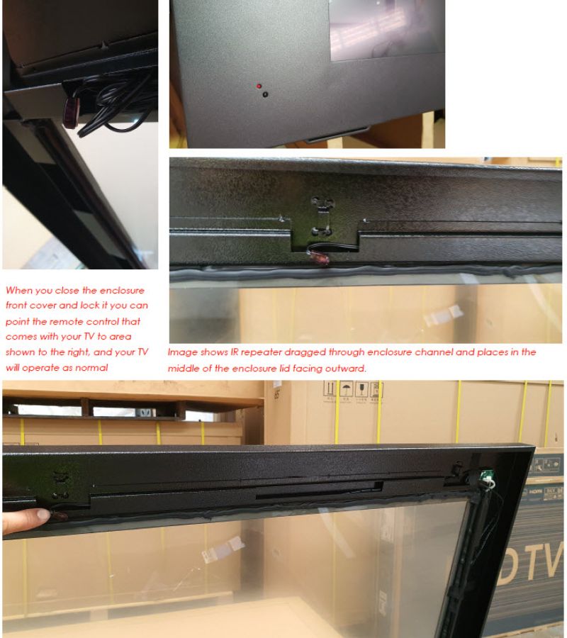
Before you close the front lift and LOCK it you should align the IR port inside the enclosure and place it in front or near your supplied TV’s IR port. This is so you can operate the TV inside the enclosure with the door closed. Depending on which model TV you have its IR receiver might be on the left, right or middle. In the example below we placed it in the middle as the Samsung TV had it’s IR in the middle.
2. Locate the IR repeater device under the front cover of the enclosure you will see an IR repeater wrapped up.
3. Relocate it to the left, right or middle of the top of enclosure lid. Peel off back adhesive and stick it to the steel (inside the steel of course) tidy up any excess cabling from the IR repeater, image below shows we fed the cable though a channel)
4. Now close the front door. Turn on the enclosure and test the IR and check it operates the TV when enclosure door is shut. If not, please relocate the IR again this time making it closer to your TV’s IR. This might take a few attempts.
5. If it all WORKS ok then you now need to lock the front door.
GUIDE 7. Switching between IP65 to IP56
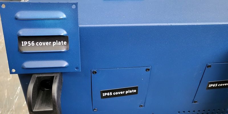
By default the enclosure is IP65 certified. However there are interchangeable squares that are vented so you can allow more air flow. These vents open the enclosure up slightly so you can make a IP56 enclosure. The IP56 hot swap vents are inside the spare parts pack and clearly labelled. You can swap out all vents or just some, the choice is yours. Make sure in landscape mode the vents are facing the downward direction and the same direction in Portrait mode.
GUIDE 8. Internal Vertical AV Mounts
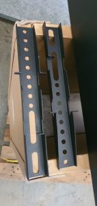
All enclosures come with vertical AV mounts that are designed for installation onto the back side of the customers TV. Once connected to the VESA stud pattern on the backside of the TV, the TV can be installed onto the horizontal mount inside the enclosure.
GUIDE 9. Internal Enclosure Bracket
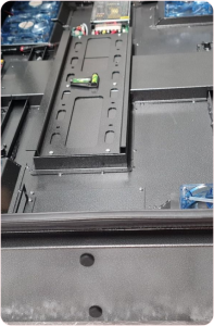
Each TV enclosure comes with a preinstalled internal AV mount. This internal AV mount can be rotated for portrait mode installations. It has built in spirit levelling to make installations easy.
NOTE: Cable entry or penetrations into the enclosure
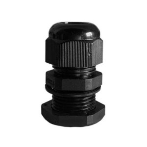
The only cable by default that goes in and out of the enclosure is power. This has been supplied and installed by the manufacturer • You are not permitted to make penetrations into the enclosure. • This voids your warranty • We cannot supply cable entry, as it does not pass IP certification • Should you wish you penetrate the enclosure for ‘other’ cables like HDMI, Ethernet or Coax then you must do this on the south side or underside of the enclosure. • You must use a IP Gland which has a rubber grommet on the inside of the connector • You must use silicon on the inside and outside of the hole that has been created
NOTE: Direct Sunlight Applications
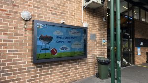
The image below shows a TV enclosure that has a 3M prestige 70 film applied to the enclosure viewing window. Not all enclosures come with the 3M prestige 70 installed. This comes at an extra cost.
Our enclosures are mainly supplied in black and for that reason we do not warrant direct sunlight installations unless you have consulted with us prior to purchase and we may have advised against it, or you have paid for the 3M prestige applicator or provided some shroud or semi shaded solution.
Direct sunlight projects without prior consultation will void warranty and will cause overheating and possibly damage to the customers supplied TV.
NOTE: Enclosure Limitations & Precautions
Please take note of the following prior to installing & setting up the TV Enclosure
1. The TV Enclosure provides ‘limited’ waterproofing, it is not fully waterproof. It is certified IP56
2. The TV Enclosure provides ‘limited’ impact resistance, it is not fully impact resistant. It is certified IK10
3. An IP rating means that under test conditions the product is protected against quantities of dust that could interfere with the normal operation of the product but is not fully dust tight.
4. The enclosure should be installed under a shroud or a cover or similar.
5. We do not warrant any electrical conduits that are made into the enclosure. In all instances an IP gland and silicon must be used but if drilling or penetrating the enclosure you are aware that it voids the warranty supplied with your product.
6. Other cables that need to enter the enclosure are carried at the customers risk or the electrical contractor who is going to make the penetrations.
7. All penetrations, if any that are made by the installer or customer must be made on the underside of the enclosure or facing south of the enclosure.
8. Overheating is the responsibility of the customers to manage & monitor.
9. You are not permitted to modify the enclosure. If change is made to the product, then you must seal with silicon or an alternative technique to safeguard and protect the components inside the enclosure.
10. Modifications to the enclosure such as conduits, changes to fans, or any other changes to the products default configuration voids your manufacturer’s warranty 11. Our protective TV enclosures can be installed in most locations under sunlight but are not recommended for direct sunlight applications. Direct sunlight applications void your manufacturer’s warranty.
12. We recommend the product is installed by a minimum of 2 people.
13. We provide no guarantees on overheating, each TV that is installed in the enclosure and the location of each enclosure installation is different. For those reasons we cannot control overheating.
14. We do not warrant any items that are placed inside the enclosure. Items placed inside the enclosure are not purchased from Octopus TV Enclosures. We are not aware of the items placed inside the enclosure, this is the customers risk and decision to place 1 or multiple items inside the enclosure.
# Note paint finish does not currently have a ‘anti-corrosive’ OR salt water primer – therefore if you live near the ocean, have a salt water pool or spa bath the enclosure will rust in a short period of time. We do not warrant against close contact to salt water, close contact defined as within 6km.
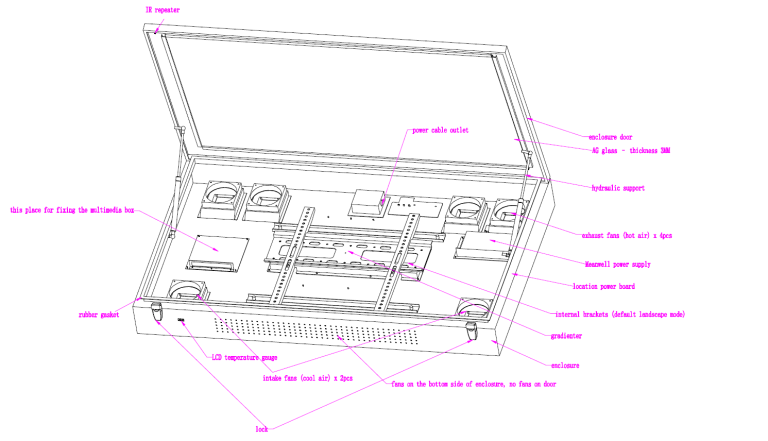
NOTE: Enclosure ID Chart
• IR repeater
• Power cable outlet
• Hydraulic arms
• Media player shelf
• Rubber gasket
• LCD Temperature gauge
• Intake fans
• Spirit leveller
• Internal bracket (landscape default)
• Power board with USB
• Power supply
• Exhaust fans
• AG glass
• Drainage Holes/plugs
